Die Application Gallery bietet COMSOL Multiphysics® Tutorial- und Demo-App-Dateien, die für die Bereiche Elektromagnetik, Strukturmechanik, Akustik, Strömung, Wärmetransport und Chemie relevant sind. Sie können diese Beispiele als Ausgangspunkt für Ihre eigene Simulationsarbeit verwenden, indem Sie das Tutorial-Modell oder die Demo-App-Datei und die dazugehörigen Anleitungen herunterladen.
Suchen Sie über die Schnellsuche nach Tutorials und Apps, die für Ihr Fachgebiet relevant sind. Beachten Sie, dass viele der hier vorgestellten Beispiele auch über die Application Libraries zugänglich sind, die in die COMSOL Multiphysics® Software integriert und über das Menü File verfügbar sind.
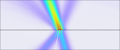
This shows how a Gaussian beam incident on a periodic structure can be efficiently simulated. This could be applied to structured surfaces like metasurfaces or diffraction gratings. Because of superposition, only a single unit cell needs to be simulated. This can provide extremely ... Mehr lesen

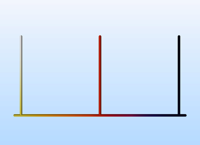
Substrate Integrated Waveguides (SIW) can be used in antenna applications. Leaky waves from a slot array on the top surface of the SIW in this model generate a beam in a certain direction that can be steered by choosing a different operating frequency. Mehr lesen

Microstrip filters can be fabricated directly on a printed circuit board (PCB) with a microstrip line going from the input to the output. Along the microstrip line there are a number of stubs of certain lengths and widths. The design of the filter involves choosing the impedance of the ... Mehr lesen

One way to generate circular polarization from a microstrip patch antenna is to truncate the patch radiator. This model is tuned around the GPS frequency range. The axial ratios are calculated to show the degree of circular polarization. Mehr lesen

In this tutorial, an uncertainty quantification analysis is performed on the Microstrip Patch Antenna model from the RF Module Application Library to explore how variations in input parameters, such as material properties or geometric variations, impact the antenna’s performance in terms ... Mehr lesen

Transmission lines are used when the frequency of the electromagnetic signals is so high that the wave nature of the signals must be taken into account. A consequence of the wave nature is that the signals are reflected if there are abrupt changes of the characteristic impedance along ... Mehr lesen
One way to design a filter is to use the element values of well-known filter prototypes, such as maximally flat or equal-ripple low-pass filters. It is easier to fabricate a distributed element filter on a microwave substrate than a lumped element filter, since it is cumbersome to find ... Mehr lesen

Some conventional three-port power dividers are resistive power dividers and T-junction power dividers. Such dividers are either lossy or not matched to the system reference impedance at all ports. In addition, isolation between two coupled ports is not guaranteed. The Wilkinson power ... Mehr lesen

It is possible to engineer the structure of materials such that both the permittivity and permeability are negative. Such materials are realized by engineering a periodic structure with features comparable in scale to the wavelength. It is possible to model both the individual unit cells ... Mehr lesen

A plane electromagnetic wave is incident on a metallic sphere partially embedded on a substrate. In this electromagnetic scattering problem, the far-field variables are computed for a few elevation angles of incidence. Mehr lesen