Discussion Closed This discussion was created more than 6 months ago and has been closed. To start a new discussion with a link back to this one, click here.
Creating a parametric geometrical layout
Posted 11.03.2021, 05:17 GMT-5 LiveLink for MATLAB, Geometry, Parameters, Variables, & Functions Version 5.6 4 Replies
Please login with a confirmed email address before reporting spam
Dear Everyone,
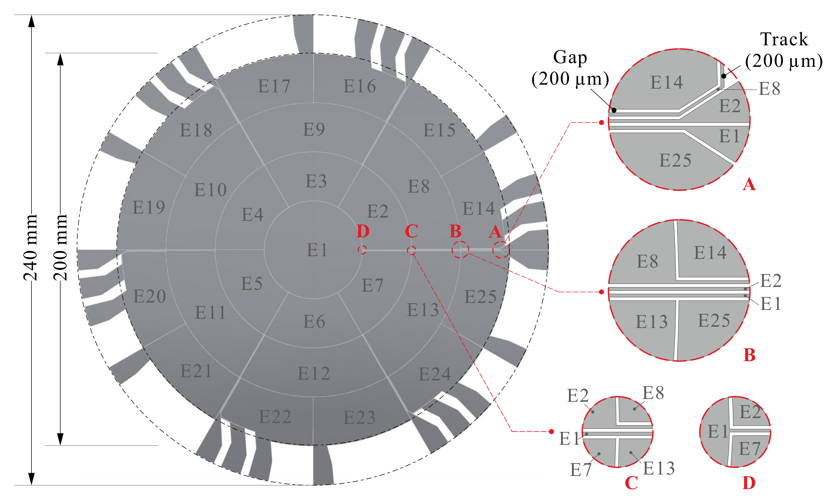
I am trying to simulate a spherical membrane, which will be deformed by pressure loads in specified areas. I am having some trouble with the generation of the geometry. The pattern in which loads will be applied will be as shown in the Figure:
 [1]
[1]
Of course the creation of such geometry is straight forward (the gaps, tracks etc can be ignored, I am just concerned with the areas E1,E2,E3...). However, I would like the generation of the layout to be highly automatic, ideally such that the amount of rings, and the amount of electrodes in each ring can be specified, and are then automatically generated and assigned a parameter for their pressure load. I am already using the MATLAB interface for some things, so perhaps this is also the way forward.
Right now I am manually creating the layout on a work plane and then extruding it, then making a "Partition Objects" operation to get selectable domains on the curved membrane. I think the generation of this layout is not so difficult using the MATLAB interface, but then when the layout is generated I really have no clue how I will select the correct areas and assign them a load? Since COMSOL just seems to name selectable boundaries 1,2,3.....n.
Any ideas you have as to how this may be done in a fully or semi automatic manner, I would be most grateful for.
Kind regards Carl Johan
- Wang, K.; Godfroid, T.; Robert, D.; Preumont, A. Adaptive Shell Spherical Reflector Actuated with PVDF-TrFE Thin Film Strain Actuators. Actuators 2021, 10, 7. https://doi.org/10.3390/act10010007
