Use of COMSOL Multiphysics® Simulation Software in High Voltage Electronic Transformers Design
High Voltage Electronic Transformers operate at high frequency, typically in a range of tens-to-hundreds of kHz. Knowing and tuning their parasitic parameters is an important aspect at the design phase. Although a vast amount of analytical means is available for calculating parasitics, field simulations, especially in 3D, come to front as the ultimate tool for attaining high accuracy. Two simulation groups in transformer design are ubiquitous: electrostatic and magnetic, using the Magnetic Fields interface. The first is useful mostly for insulation design. (Transformer parasitic capacitance cannot be derived directly from the electrostatic field.) Unless non-linear media are involved, electrostatic simulations are rather trivial. The second group can yield magnetizing, leakage, and mutual inductances. Same, and also parasitic capacitance, can be derived from electromagnetic simulation (Magnetic and Electric Fields interface). We focus on the second group.
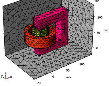
Relation of the transformer magnetic field to the transformer equivalent circuit is revisited. Difference in derivation of leakage inductance from static and frequency-domain analyses is illustrated. 3D versus 2D analyses are compared. It is shown that 3D simulation provides much more accurate results for U-core-based transformers with windings situated on different legs. A method of calculation of mutual inductance based on matched and opposite connection of windings is compared to those described in blog [1]. It is particularly useful for weakly-coupled coils in air-core transformers. Transformer optimization for operation in a resonant circuit is illustrated on an example of such a transformer [2]. Sweeping parameters, such as number of turns, windings’ height and width, values of resonant capacitors, etc., in a wide range, we can arrive to a desired design point. Here, the Magnetic Fields interface and Electrical Circuit interface are mainly used. Distribution of electric field in multisectioned windings and parasitic capacitance of the transformer is calculated in the Magnetic and Electric Fields interface using RLC Coil Group features.
In practical use, the transformer is close to sensitive circuitry and/or metal construction elements. Then knowing fringe fields comes useful. Direct calculation of eddy current losses is compared to analytical estimates. Methods of alleviating the induction heating effect are discussed.
Most of the above simulations are pitted against experimental evidence, showing their fair match. (In some cases, it is difficult to judge which is more accurate.)
Herunterladen
- pokryvailo_paper.pdf - 1.73MB