Updates im AC/DC Module
Neue Formulierung für das Interface Electrostatics
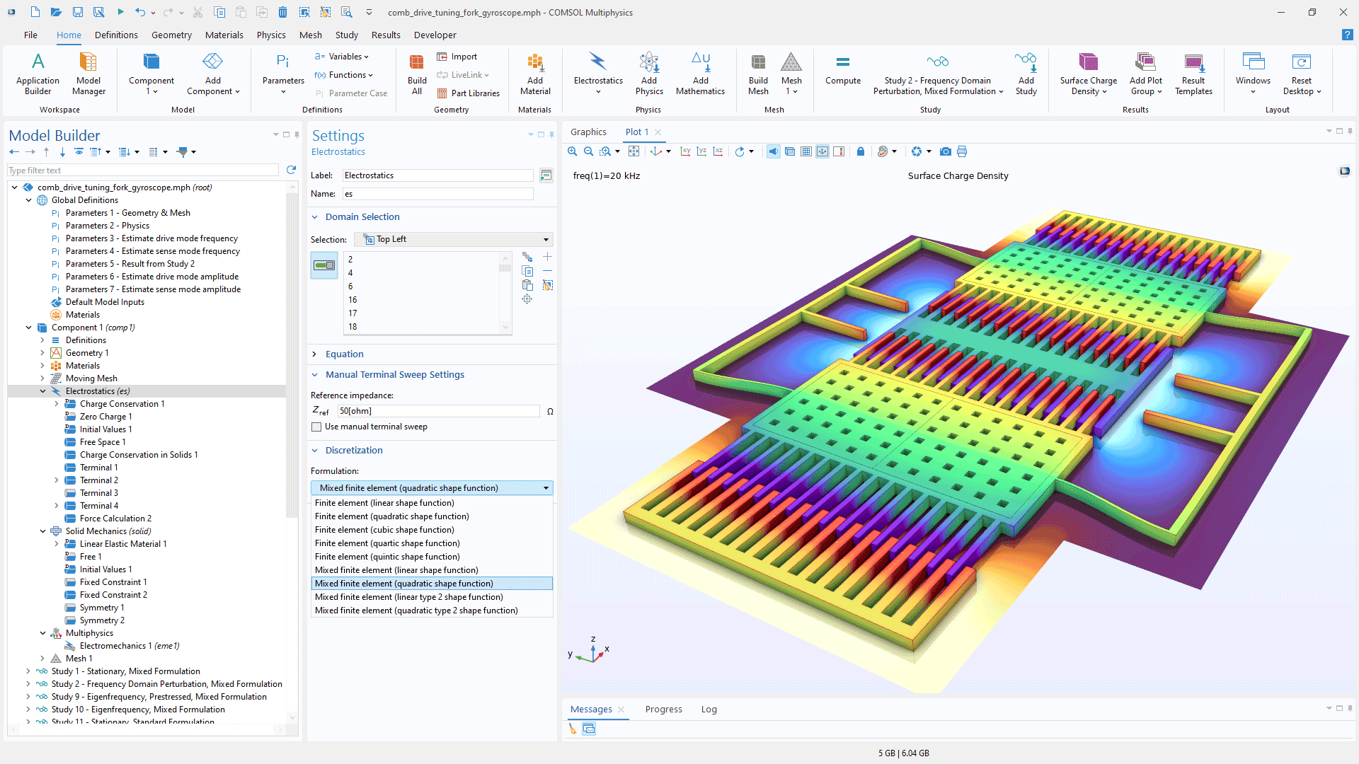
Das Interface Electrostatics enthält jetzt eine neue Gleichungsformulierung für die genauere Berechnung elektrostatischer Kräfte, was besonders bei der Modellierung von MEMS wie Beschleunigungsmessern und Gyroskopen nützlich ist. Durch die direkte Lösung des elektrischen Verschiebungsfeldes verbessert dieser Ansatz die Genauigkeit in Geometrien mit scharfen Ecken und ermöglicht genauere Kraftbewertungen selbst bei gröberen Netzen. Im Gegensatz zur herkömmlichen potentialbasierten Formulierung verwendet die neue Methode eine gemischte Formulierung, bei der zwei Gleichungen gelöst werden, eine für das elektrische Verschiebungsfeld (D) und eine für das elektrische Potential (V). In Version 6.3 ist diese verbesserte Formulierung als Option Mixed finite element für 2D- und 3D-Elektrostatik verfügbar. Mixed finite element ist die Standard-Diskretisierungsoption für die Interfaces Electromechanics, wenn das MEMS Module oder das AC/DC Module in Kombination mit dem Structural Mechanics Module verwendet wird. Diese neue Formulierung ist im Tutorial-Modell Micromachined Gyroscope with Mixed Formulation zu sehen.
Umfassende Unterstützung für die Modellierung der Dispersion, einschließlich biologischer Gewebe
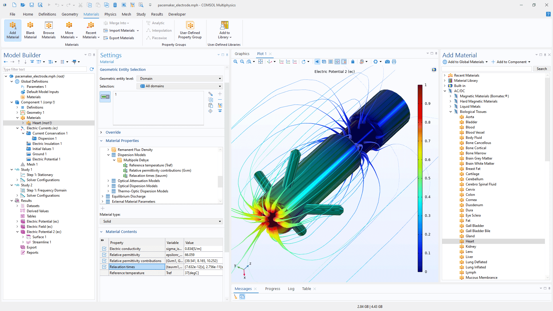
Sowohl für das Interface Electrostatics als auch für das Interface Electric Currents stehen drei neue dispersive dielektrische Materialmodelle zur Verfügung: Cole–Cole, Havriliak–Negami und User defined. Diese Modelle sind sowohl für Frequenzbereichsstudien als auch für transiente Studien verfügbar. Die Modelle basieren auf der in der vorherigen Version eingeführten Funktion Partial Fraction Fit, was bedeutet, dass die dispersiven Materialien auch direkt an gemessene Daten angepasst werden können.
Darüber hinaus kann das vorhandene dispersive Materialmodell Multipole Debye in Kombination mit Materialdaten im neuen Ordner Biological Tissues in der AC/DC Module Material Library verwendet werden. Dieser Ordner enthält Werte für die elektrische Leitfähigkeit, die relative Permittivität und die Referenztemperatur sowie die Relaxationszeiten und die Beiträge zur relativen Permittivität mehrerer Debye-Pole für 54 biologische Gewebetypen. Diese Materialdaten sind besonders nützlich für medizinische Anwendungen.
Modell für hochfrequente Verluste und homogenisierte Litzenspulenleiter
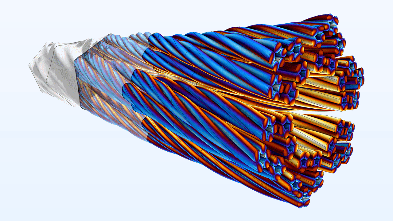
Das Leitermodell Homogenized multiturn im Feature Coil enthält jetzt ein Modell High-frequency effective loss, das standardmäßig aktiviert ist. Im Frequenzbereich weist dieses Modell eine effektive Drahtleitfähigkeit und eine komplexe Permeabilität zu, um die Feldverteilung und den Wechselstromwiderstand einer vollständig aufgelösten Spule unter Berücksichtigung von Skin- und Proximity-Effekten zu modellieren. Darüber hinaus verknüpft eine neue Option Wire properties namens From resistance and mutually coupled circuit die Spule mit einem internen Schaltkreis, um induktive Verluste sowohl im Zeit- als auch im Frequenzbereich zu simulieren.
Das Leitermodell Homogenized litz coil unterstützt den Verlust bei hohen Frequenzen und ermöglicht die Angabe der Litzenzahl und des Gleichstromwiderstands pro Längeneinheit, wodurch der durch Verdrillungsmuster hinzugefügte Widerstand ausgeglichen wird. Darüber hinaus kann der Litzendrahtwiderstand pro Längeneinheit mithilfe von Spezifikationen, Messungen oder frequenzabhängigen Ausdrücken festgelegt werden.
Die folgenden Tutorial-Modelle veranschaulichen diese neuen Features:
Neues Feature Laminated Core
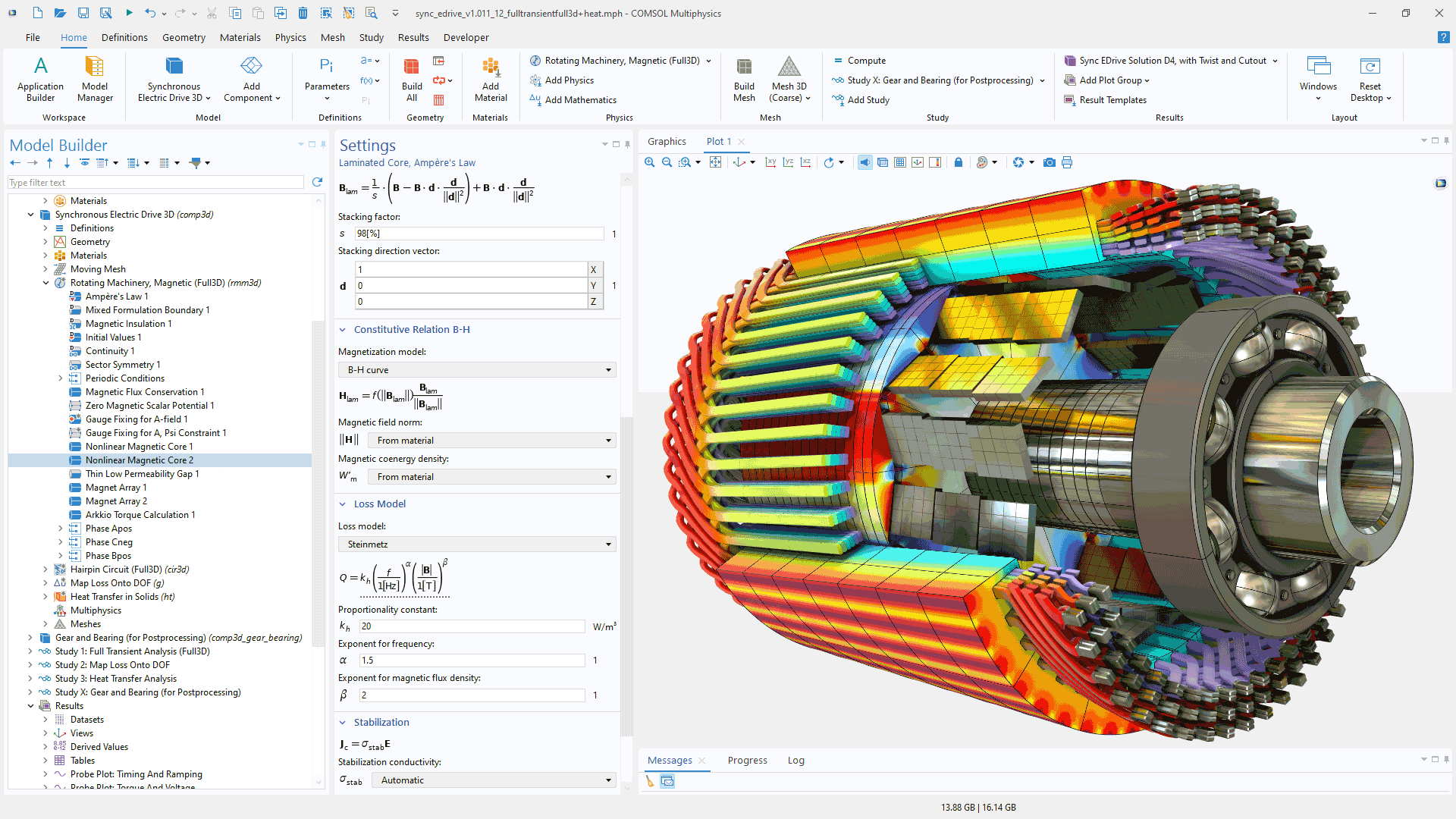
Das neue Feature Laminated Core ermöglicht durch die Approximation der Lamellen als anisotropes effektives Medium die effiziente Modellierung von laminierten Kernen in Transformatoren, elektromechanischen Aktoren und Elektromotoren. Das Feature unterstützt sowohl lineare als auch nichtlineare magnetische Eigenschaften, einschließlich Relative permeability, B-H curve und Effective B-H curve. Um das Verhältnis von magnetischem zu nichtmagnetischem Material anzugeben, kann Stacking direction festgelegt und Stacking factor angepasst werden. Darüber hinaus können Widerstands- und Magnetverluste mithilfe empirischer Modelle wie den Modellen Steinmetz oder Bertotti einbezogen werden. Das Feature Laminated Core ist in den Interfaces Magnetic Fields; Magnetic Fields, No Currents und Rotating Machinery, Magnetic verfügbar.
Die folgenden Tutorial-Modelle zeigen das Feature Laminated Core:
Verbesserte Benutzerfreundlichkeit für Verbindungen von Schaltungen
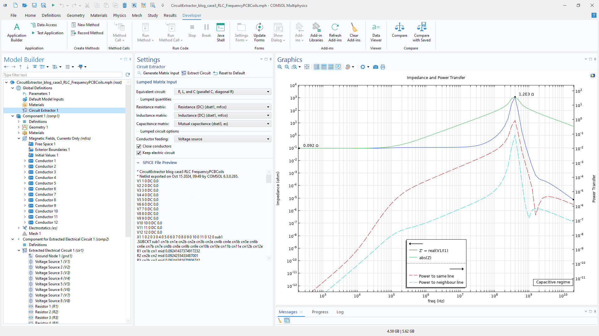
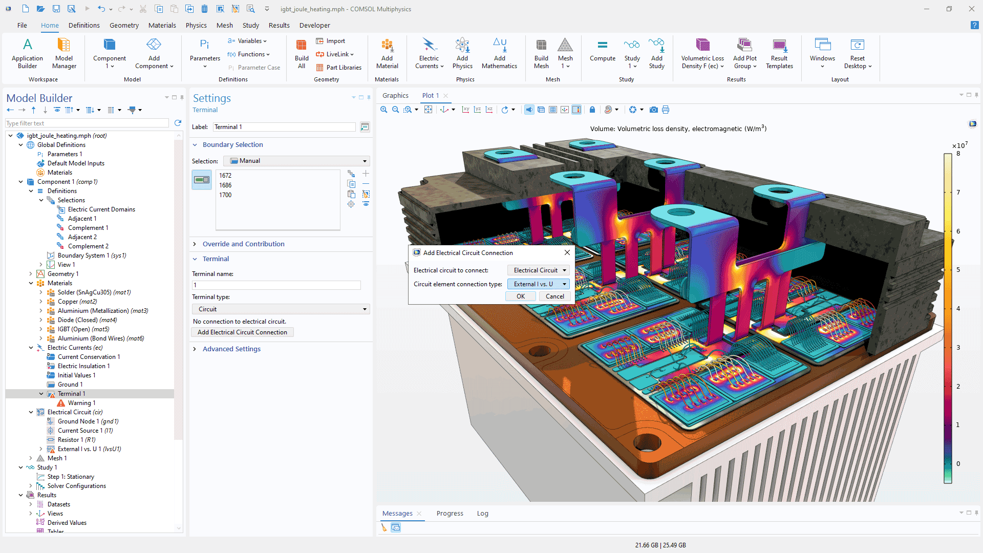
Die Benutzerfreundlichkeit von Verbindungen zwischen Schaltungen wurde erheblich verbessert, sodass es einfacher ist, mithilfe der Features Terminal und Coil Features von Gebieten zu verbinden, wie das Interface Electric Currents oder Magnetic Fields mit dem Interface Electrical Circuit. Die automatisierte Funktionalität übernimmt nun das Vervollständigen von Schaltungsverbindungen, wenn ein Gebiet oder ein Rand mit einer elektrischen Schaltung verbunden wird. Darüber hinaus sind die Import- und Exportfunktionen für Schaltungen jetzt über die COMSOL API for use with Java zugänglich, sodass Apps, Modellmethoden und Add-Ins automatisch Schaltungen abrufen oder exportieren können. Dies ist besonders nützlich für die Extraktion von Lumped-Schaltkreisen, welche auf der Grundlage von Widerstands-, Kapazitäts- und Induktivitätsmatrizen generiert werden, die aus Finite-Elemente-Modellen abgeleitet werden. Die folgenden Tutorial-Modelle zeigen diese neuen Verbesserungen:
Neue Multiphysik-Interfaces Elektromechanics
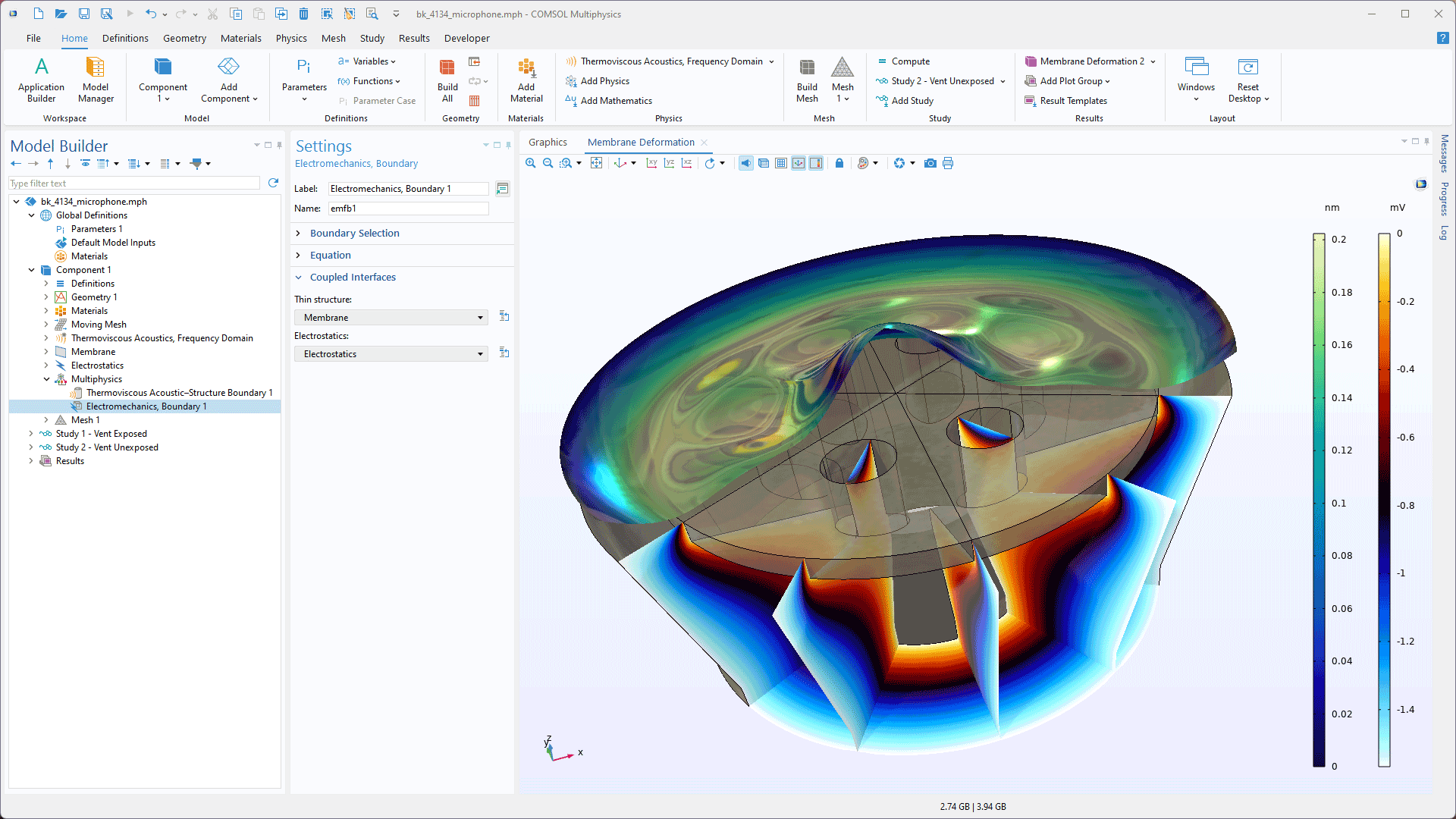
Die neuen Interfaces Electromechanics, Shell und Electromechanics, Membrane vereinfachen die Modellierung der Verformung dünner Strukturen, wie Mikrofonmembranen, die durch elektrostatische Kräfte beeinflusst werden. Diese Interfaces enthalten automatisch die Multiphysik-Kopplung Electromechanics, Boundary für die nahtlose Integration mit Schalen- oder Membranelementen und verwenden das Interface Electrostatics zur Modellierung des elektrischen Feldes. Die Interfaces, die in den Tutorial-Modellen Brüel & Kjær 4134 Condenser Microphone und Axisymmetric Condenser Microphone demonstriert werden, erfordern auch das Structural Mechanics Module.
Neue und aktualisierte Modelle, neue App und neues Add-In
COMSOL Multiphysics® Version 6.3 bietet neue und aktualisierte Modelle, eine neue App und ein neues Add-In für das AC/DC Module.
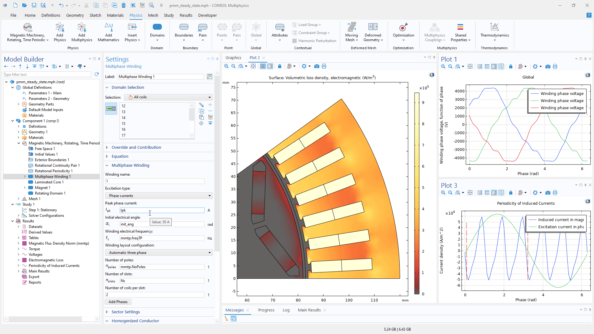
Permanent Magnet Motor in Steady State
Application Library Titel:
pmm_steady_state
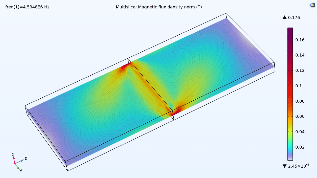
Piezomagnetic Cell Rover
Application Library Titel:
piezomagnetic_cell_rover
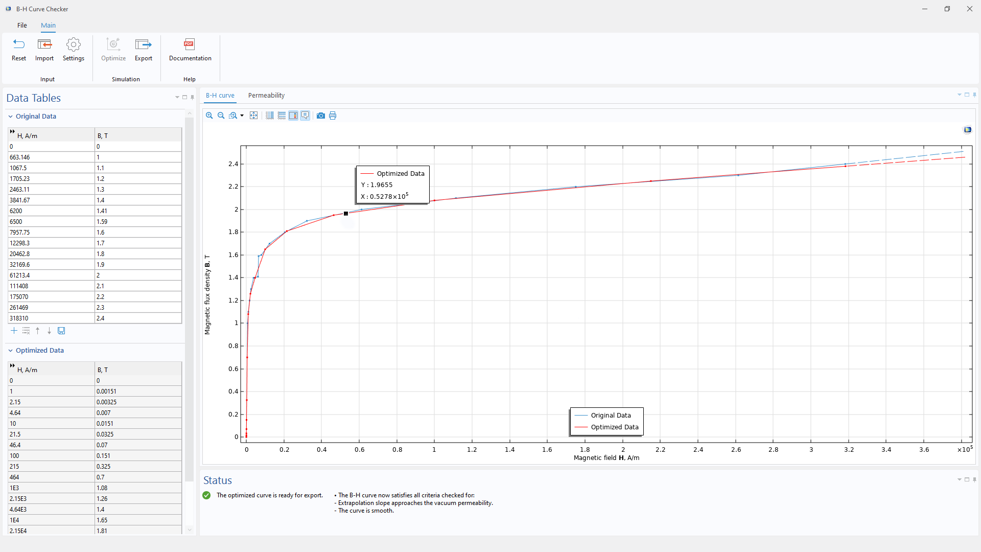
B-H Curve Checker App
Application Library Titel:
bh_curve_checker
Circuit Extractor Add-In
